
DIY Components
The Three System Components – Processor, Motherboard, and Graphics Card
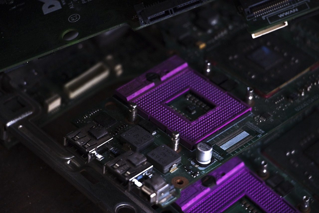
The processor is the absolute core of a computer, with its main function performing general-purpose calculations and schedule other hardware to perform calculations. AMD and Intel are the dominant players in the current consumer market, while other processor manufacturers mainly focus on the server and commercial sectors. If you’re building a computer for gaming, I would recommend the AMD R7-7800X3D and the R5-5600X3D. After all, for the same level of performance, the cost of the corresponding power supply and cooling for an Intel processor would be at least two price tiers higher. The R7-7800X3D is simply divine for gaming processors.
AMD’s consumer-grade processors are now available in AM4 and AM5, with AM4 processors in PGA (Pin Grid Array) with 1331 pins and AM5 processors in Land Grid Array with 1718 pins. Intel’s current consumer processor specification is Land Grid Array 1700 with 1700 pins. The number of pins can have an impact on the physical size of the processor, as Intel’s upgrade from Land Grid Array 1200 to Land Grid Array 1700 has resulted in the need for new brackets for mounting heat coolers. On the AMD side, both AM5 and AM4 use the same mounting brackets, so older coolers can still be used directly.
Whether or not to use third-party fasteners depends on the specific processor. First of all, AM4 processors do not have this problem, the original fasteners directly dry on the end; the use of the original fasteners is really more likely to leak silicone into these recesses, whether or not to use a third-party fasteners for heat dissipation and virtually no impact, so I personally feel that AM5 processors can be matched with; Intel 12, 13, 14-generation processors are recommended to directly replace, after all, the two bending moments of the different, long time really will bend.
The external devices of existing consumer-grade microcomputers are mounted on the motherboard to realize their functions. The main versions available on the market are mini-ITX, micro-ATX, and ATX, and the specifications of each version are as follows:
mini-ITX measures 170mmx170mm and is more expensive than the other versions, but has the lowest external expandability, with only two memory slots and one PCIe x16 slot.
The mATX sizes are 245mmx245mm, 245mmx225mm, 245mmx185mm and a few more. The ATX version is the most popular choice, with four memory slots, two PCIe x16 slots (physical specs, may be x16+x4 by pinout) and multiple M.2 hard drive bays.
The entire motherboard is designed around the processor, which comes in different physical forms, such as AMD’s latest AM5 dock, while previous generations of Razorbacks were AM4 sockets. Intel’s latest two generations of processors are the Land Grid Array 1700, and earlier there were the Land Grid Array 1200, Land Grid Array 1151, and these docks. The latest two generations of Intel processors are the Land Grid Array 1700, Land Grid Array 1200, and Land Grid Array 1151. Both slots and docks have their own anti-dumbing designs, but don’t do miracles and don’t touch these pins with anything other than the processor.
ATX sizes of 305mmx244mm and mATX versions are the most popular options, typically with four memory slots, three PCIe x16 slots (physical specs, which may be x16+x8+x4 by pinout) and multiple M.2 hard drive bays. Some of the larger sizes are labeled as EATX, but do not actually meet EATX specifications (width, 8 memory slots, etc).
Each of them is generally labeled according to the pattern of “brand (big series) + chipset (version) + brand series (sub-series) + other suffixes”, in which the brand series may be mentioned in the front.Intel has four grades from high to low: X, Z, B, H. AMD has three grades from high to low: X, B, A. The high-end series are X399, X670, X570, and so on. The high-end series are motherboards such as X399, X670 and X570.
The motherboard’s power supply is not a matter of how many capacitors and inductors are counted, take the model NCP81530R power supply PWM controller as an example, check the corresponding datasheet to see that it is an 8+2-phase power supply controller. In the flagship design, the 8 phases of this controller are paralleled to create a 16-phase power supply, and a separate 2-phase is paralleled to create a 2-phase, resulting in a total of 16+2+1 phases of power supply. The 16 phases that can be used for the processor are the 16 phases paralleled by the native 8 phases, and the additional phases that follow are for memory and core graphics. The load capacity decreases at high temperatures, which is why manufacturers prefer to parallelize the power supply.
Like flagship motherboards can easily be small 20 MOS tubes full, the use of heat dissipation is naturally a big problem. So now the motherboard is basically thermal armor full, full coverage of power supply, full coverage of the chipset, full coverage of the main M.2 hard disk space. However, many previous motherboard thermal armor is a decoration, there is no thermal pad, is suspended over the MOS tube and chip, the use of the effect is not even as good as bare. Now the thermal armor has a standard cooling pad to ensure that the heat of the corresponding components can be quickly exported.
The size of the backplane is the same for all different levels of motherboards, but of course the specs and number of ports on the backplane are based on the class and design ideas of the motherboard. The ASUS ROG CROSSHAIR X670E HERO, for example, offers as many as four USB-C ports on the back panel, two of which support 40Gbps, one supports 20Gbps, and one supports 10Gbps.
Graphics card is to bear the output graphics display components, the display chip, video memory and peripheral circuitry into a separate board is a stand-alone graphics card, need to be connected to the motherboard through the universal expansion slot/interface; display chip integrated in the processor, not made into a separate independent board is the core graphics card. The consumer graphics card market is divided among AMD, Intel, and Nvidia, but there are also newer brands like Moore Threads.
The performance and specifications of discrete graphics cards are basically far better than their core counterparts, except for GT1030s, which are “unplugged” to boost performance. As performance increases, power consumption naturally rises, and the accompanying cooling system is naturally bigger, thicker, and longer. New graphics cards are basically starting with two slots and three fans, and dual-fan and single-slot cards are basically extinct. A lot of classic ITX chassis also do the graphics card to support the thickness and length of the adaptation, with a single fan or dual-fan card with a small chassis there is really no need to update.
As the performance of the nuclear display increases, low-end unique display is no longer in the consumer market, the current stage of the unique display specifications are very high, basically need independent power supply. In my hands RX 7900XTX, RTX4090, A770, RTX4070 four cards, for example, RTX 4090 is ATX3.0 power supply interface, able to provide 600W of power; RX 7900XTX is a 3-way PCIe 8Pin power supply, Arc A770 is a 2-way PCIe 8Pin power supply, RTX 4070 is a single-way PCIe 8Pin power supply, a single 8Pin power supply, a single 8Pin power supply, a single 8Pin power supply, a single 8Pin power supply, a single 8Pin power supply, a single 8Pin power supply, a single 8Pin power supply. The RX 7900XTX is a 3-way PCIe 8Pin, the Arc A770 is a 2-way PCIe 8Pin, and the RTX 4070 is a single PCIe 8Pin. However, to be honest, the three 8Pin native cables are really too crowded, so if you have the conditions, try to switch to customized cables.
Memory and Hard Disk
Memory is used for temporary storage of data issued by the processor and data retrieved from external storage such as hard disk, most of the data of the computer run by the memory is responsible for throughput read and write, the mainstream choice at this stage is DDR4 and DDR5 memory, AMD processor, desktop AM4 motherboards are DDR4 DIMM memory, AM5 motherboards are DDR5 DIMM memory, mobile 6000 series corresponding to pluggable memory motherboards are DDR4/5 SO-DIMM both, mobile 7000 series processor corresponds to all DDR5 SO-DIMM, DDR4/5 SO-DIMM. AMD processors, desktop AM4 motherboards have DDR4 DIMMs, AM5 motherboards have DDR5 DIMMs, mobile 6000-series motherboards have DDR4/5 SO-DIMMs, and mobile 7000-series processors have DDR5 SO-DIMMs; Intel’s side of the equation is that there are DDR4 and DDR5 versions of every generation of mid-range and low-end motherboards, and high-end motherboards are mainly DDR5-based.
With the current processor performance, Intel 12 and 13 generation processors directly buy high-frequency strips, a key to open the XMP on the end of the manual overclocking with the processor, the motherboard’s physical relationship is also very large, the actual operation is still quite troublesome. AMD this side of the trouble, direct 6000MHz to 6400MHz memory sticks directly with the good. The only thing you need to pay attention to is that the radiator will limit the height of the memory, air-cooled can be solved by replacing the fan position, water-cooled limitations are generally not good solution.
Hard disk is a non-volatile memory, the user computer data are stored on the hard disk. DIYer can buy and use the hard disk on the consumer motherboard only accounted for a part of the hard disk, according to the storage medium and the way to be able to be divided into mechanical hard disk and SSD, according to the form of the interface to be able to be divided into M.2 hard disk, PCIe hard disk, SATA hard disk, U.2 hard disk. However, due to the vast majority of users, the latter three types of hard disk has rarely appeared in the DIY, so do not do in this article to expand.
M.2 drives were very confusing in previous years, with various pairings of buses, transfer protocols, electrical interfaces and physical interfaces, but in reality they weren’t fully compatible and would conflict. In the past two years it has been unified by the M Key interface with the PCIe x4 protocol, and the only difference is the iteration of the PCIe protocol. The only difference is the iteration of the PCIe protocol. Depending on the capacity and price requirements, as long as the price is cheap enough, any problems with this drive are my own. 2280, 2242, 2230 and 22110 M.2 hard drives are also available in several different lengths, but of course, the latter three are seldom the ones you’d choose.
With the hard disk read and write speed climbing, PCIe 5.0 protocol solid state sequential read and write can be to 10G/s or more. Heat generation called a rising boat, the vast majority of hard disk will be due to high temperature drop speed, so most of the motherboards are equipped with heat dissipation armor. However, the motherboard’s own armor cooling ability compared to the flagship solid state heat generation may still be small, may have to change a heat pipe cooler like Limin HR-09. Of course, like those secondary disk space will have to change some thinner cooler, if the first PCIe slot below the hard disk space can not even use the hard disk cooler, after all, now the graphics card are multi-slot occupancy, directly on the full block.
Case, Power Supply and Cooling
There are now many more choices for cases than there were a few years ago: the common side-panel transparent cases and the increasingly quiet ITX cases are not to be mentioned, and there is an endless stream of compact cases that cut down on unnecessary space and support full transparency on the front side, resembling a seascape. The case is fundamentally restricted by several factors such as the motherboard form factor, the height limit for air coolers, the support for water cooling radiators, and the length and slot width of the graphics card. These considerations must be taken into account from the product selection stage to avoid conflicts that could prevent configurations.
Take for example the compact chassis series of Mechanical Master, there are models that support from small ITX to large ATX versions. In the case of the C34 Pro, for example, which supports multiple versions, mounting MATX and ATX would require switching the position of the chassis steel plates, and there would also be differences in the support of some components.
See this table for specific support, which basically covers Mechanical Master’s current product line, with more component constraints for compact cases. Because of the compressed vertical height, water-cooled fans and cold rows will also have high memory limit requirements. Because of the higher space utilization, the components are more likely to interfere with each other, so the corresponding situations are labeled and explained in all of MasterCraft’s C-series chassis.
There are a lot of non-standard designs for power supplies, but the DIY market is designed according to the corresponding specifications because power supply standards were introduced very early. The common ones are ATX, SFX/SFX-L and 1U Flex. Note that a 1U power supply is not necessarily a 1U Flex power supply, and some of the 1U power supplies for servers are longer than the ones above.
To compare the size specifications, take the Kyushu Fengshen PX850G and SilverStone SST-SX600-G for example, you can find that the ATX power supply and SFX power supply are quite a bit different in terms of size. In the price is more obvious, other specifications parameters of the same power supply to compare, SFX price simply take off.
The 80 PLUS certification requirements focus on conversion efficiency and power factor (PF) at 10%, 20%, 50%, and 100% of the rated power output. Participating power supplies that meet the conversion efficiency and power factor requirements of the corresponding level will be certified at the corresponding efficiency level. “80 PLUS certification is not necessarily a good power supply, but without 80 PLUS certification it is definitely not a good power supply.” Platinum and Titanium certified power supplies are definitely good power supplies, and from Gold downwards, there are products that are just fish out of water.
According to whether the wires are removable or not, there are full-module, semi-module and non-module power supplies. Still to the Kyushu Fengshen PX850G as an example, like this is not fixed wiring and all interface power supply is a full module, corresponding to different power supply cables have different interfaces, docking of different cables, there is a separate ATX3.0 16PIN interface labeled 12VHPWR; half-module power supply generally ATX 24PIN and CPU 8PIN fixed on the power supply, PCIe 8PIN and SATA power supply, the power supply is not a good product, and from the Gold medal, there is a good product. 8PIN and SATA power supply cable modularization; non-modular power supply is all power supply cables are fixed in the power supply, no separate cable.
Modular power supply and power supply body interface has been talked about, and then look at the interface of the power supply cable. This part is connected to the corresponding interface power supply on the motherboard, in the physical specifications have not changed much, the latest ATX3.0 standard updated 12HPWR 16Pin power supply specifications. Nowadays, Telegraph basically retains the following interfaces: ATX 24Pin for motherboard power supply, 8Pin [4+4] for CPU power supply, 8Pin [6+2] and ATX3.0 16Pin for PCIe graphics card power supply, SATA power supply for hard disk power supply and specialized D-type large 4Pin power supply.
Air cooling is limited by the height of the chassis side panels, while water cooling is limited by the chassis support specifications. Different brands of coolers with different specifications also have different cooling capabilities, which results in cooling being basically the most restricted component, and can even limit the choice of processor due to the size of the chassis supporting the specifications in turn. The flagship FC140 air-cooled dual-tower cooler from Luminous is 285W, the Ice Bastion 360 from Jiuzhou Fengshen is 300W, and a single tower with five heatpipes is 180W, while a hard disk cooler is a passive cooler of about 5W. If the full load power of the processor exceeds the heat sink’s capacity, it will lead to heat buildup and downclocking.
An air-cooled cooler consists of a base, heatpipes, fins, and a fan. It relies on the evaporation-condensation of the liquid in the heatpipes to carry the heat, with the phase-change medium absorbing heat and evaporating at the base end of the heatpipes, and exothermically condensing at the fin end. The thermal conductivity of the heat pipe is hundreds of times that of copper and aluminum, and the number of heat pipes in ideal conditions can be said to be linearly correlated with the cooling efficiency, and more heat pipes equals stronger heat dissipation. In addition to the heatsink itself, the processor design, silicone grease application, chassis air ducts and ambient temperature will all have an impact on the actual heat dissipation.
The base is in direct contact with the surface of the processor, so naturally the best heat dissipation is when it is in full contact. Common process heat pipe direct contact with the copper bottom welding two: heat pipe direct contact compared to the copper bottom welding, we may want to say that this is directly connected to the heat pipe, there is no intermediate material thermal conductivity should be more efficient it. Reality and theory or there is a small gap between the heat pipe direct contact needs to be milled and ground this side of the direct contact, and then stuffed into the aluminum base of the tube. The gap between the heat pipe and the base, the smoothness of the contact surface are not hair guarantee. The copper base welding only need to mill the copper base into a smooth surface on the good, the base and heat pipe are copper, thermal conductivity is naturally more efficient.
The main function of the fins is to dissipate the heat carried from the base of the heat pipe, and there are two common processes: through-fin and reflow soldering:
Fin piercing refers to the design of “thick tube and small hole” to pass the heat pipe through the fins, because of the small opening, the fins can press the heat pipe. But after all, there is still a gap, and the expansion coefficients of copper and aluminum are different, and due to cost constraints and the lack of improved tolerances, most air-cooled radiators that use the through-fin process have poorer cooling performance and durability. The exception to this is the old Luminous model, which is a Fin-piercing monster with extremely tight tolerances to ensure thermal conductivity under direct contact.
Reflow soldering is to brush the soldering flux on the heat pipe, complete the assembly and put into the machine heating, solder melting can fill the small gap between the heat pipe and fins, but still the heat pipe and fins of different materials, a lot of reflow soldering flux need to add nickel, but nickel’s thermal conductivity is very poor, poor quality reflow soldering process products of the spreading of the thermal efficiency of the more intolerable.
So in the actual product will see, high-end flagship cooling and low-end entry cooling are used to wear Fin and reflow soldering process products, but the actual thermal efficiency and the use of the effect is naturally a world of difference.
Common air-cooled radiator forms are down-pressure type and tower type, generally speaking, the cooling performance of tower type radiator is stronger than down-pressure type. There is basically no big difference in thermal conductivity between a tower and a down-pressure type with the same heatpipe specifications, but the fin area and fan size of a tower is generally higher than that of a down-pressure type, which naturally results in higher cooling efficiency.
In many ITX or compact cases, the overall height of the cooler is limited, so often downward pressure cooling is the better choice. Of course, the net height of many tower coolers (including a good portion of dual-tower coolers) is also OK.
Water-cooled radiator consists of a cold head with a pump, a liquid guide tube, a cold plate and a fan in several parts, relying on the total liquid heat capacity of the circulating system to carry heat. The water-cooled liquid flows through the cold head to absorb heat, and the pump accelerates the flow of water-cooled liquid to release heat at the fin end. Due to the high specific heat capacity of the water cooling liquid used, the temperature of the processor will not have too obvious sudden temperature changes. In addition to the design of the cooler itself, the cooling performance is affected by the design of the processor, the application of silicone grease, the air ducts of the chassis, and the ambient temperature, just like an air-cooled cooler.
Water-cooled radiators are distinguished by the size of the cooler rows, which commonly come in 120mm, 140mm, 240mm, 280mm and 360mm sizes, all of which correspond to the specified fan specifications. However, it is important to note that the dimensions here actually correspond to the length of the cooling fins of the cold row, not the actual length of the cold row. The inlet and outlet of the cooling fins and the frame generally take up 20-50mm of the length of the cooling fins, and there is an upper limit to the cooling capacity of different sizes of cooling fins. The higher the heat generated by the processor, the bigger the cooling fins will need to be to dissipate the heat.
All-in-one water-cooled coolers have an integrated pump in the cold head, and the power supply cable needs to be connected to the CPU_FAN connector or the corresponding PUMP connector. Some water-cooled coolers also have lighting effects or a screen, so you need to connect the corresponding cable to the RGB connector or the USB built-in connector.
Plus the fan cable is even more troublesome, a fan but also a power supply and a light control, and then counting the case’s own fan, may also have to buy a separate light control hub. Of course, the design of the device is always iterative, the new fans equipped with water-cooled radiator of the God of wind support fans in series and parallel connection. Compared to the shell direct insertion fan price is lower, security and configuration difficulty is lower, after all, chassis installed fan and water-cooled installed fan is not a difficulty.
The finished product on sale are these integrated water cooling, naturally there are also on sale split water cooling. Many new motherboards and graphics cards have come out with corresponding water-cooled version, similar to this split water-cooling, you have to prepare the water pump, water pipe, water tank, cold row and install their own. This kind of configuration is very difficult, if you do not have the experience of configuring the machine, just look at other people to install, do not come up to get this kind of.
Preparation
When mounting various components, there are bound to be a lot of screws, and some good cases can basically standardize the screws, but M.2 hard drive screws still require different bits. Considering that many hard drives do not provide special screwdrivers, and most motherboards do not have M.2 quick release, it is best to prepare a screwdriver with replaceable bits. In addition, if possible, you can prepare a screwdriver with an extra-long lever to deal with deeper screws, and a power screwdriver to deal with screws that require a lot of configurations (such as the cold row). Like Mechanical Master comes with a screwdriver that is compatible with all the chassis screws it offers, so just prepare a small screwdriver for mounting the M.2 hard disk separately.
The chassis usually comes with about 10 of the smallest ties, which is barely enough for air-cooled and sweet graphics cards. But for a water-cooled + flagship graphics card, you’ll definitely need to buy a single tie, and a few big ones will have to be stroked and tied, so a rough estimate would be 20 to 30 to get enough.
We also need a USB flash drive to set up the system, either using the official Media Creation Tool to set up directly to a USB flash drive, or using WePE with a downloaded image. How to choose a USB flash drive? There are only two criteria: fast enough reading speed and good compatibility of the host controller. Using this kind of DIY USB flash drive can get very fast reading speed, but sometimes compatibility is really a problem. If you have more sporadic needs, just choose a branded USB flash drive. Lexar V400 64G version is sold for 30 bucks, and the read speed can reach 100MB/s, that is good enough.
According to the order of different chassis, the process can be broken down into 7 major steps: disassembly and adjustment of the chassis, the motherboard and its components, cooling, the power supply, wiring and cable management of the entire machine, the graphics card and lighting and operating system. On different cases, the order of the above steps may be different, and the actual operation overlaps. This job is a skilled labor, installed once without psychological burden, the subsequent no matter what chassis configuration will be able to handle it. Just need to confirm the interference relationship between the components to ensure that the components will not affect each other.
Relatively large chassis is okay, extremely adequate space minimized, but compact small chassis should pay attention to component interference. In the case of the MasterCraft C26 Cube, for example, the chassis ultimately affects the processor selection: the height of the air-cooled cooling is limited, which limits the cooling capacity and ultimately affects the processor selection; the size of the water-cooled cooling rows is limited, which limits the cooling capacity and ultimately affects the radiator selection. The cooling model affects the length of the power supply, and the different length of the power supply affects the length of the graphics card, which in turn affects the selection of the graphics card.
The motherboard
Mounting the CPU only needs to pay attention to the processor’s pins and direction, to ROG X670E this AM5 motherboard as an example, open the fastener and observe can be found to show the direction of the illustration, for example, the upper left corner of the base is a straight cut, and the other three corners are made into rounded corners.
The AMD Ryzen 7800X3D, a BGA processor, is labeled with an arrow in the upper left corner. With these two points we can match the orientation of the processor to the base, and then press the original fasteners to install the processor in place. Installing Intel’s processor is a similar operation, but the I-series motherboards are differentiated by the “pits” marked on the plastic base.
AMD’s consumer-grade processors also maintain their basic square dimensions, and the torque is basically the same in both directions, so there’s no potential for processor distortion. However, Intel processors have become rectangular since the 1700, and there have been cases of processor deformation, so for safety and peace of mind, it is better to use a third-party fastener.
Taking the ROG M12H and AMD3900X as an example, the snapping mode is different, and the way of opening is different. The orientation is still the same as labeled and manually aligned mounting, using the motherboard orientation as a reference, more AM4 processor slots are landscape, while AM4 and Intel 1700 are mostly portrait.
In between the CPU chassis and the first PCIe slot is the hard drive bay that goes straight to the CPU. The orientation of the hard disks varies from motherboard to motherboard, but that’s about it. The notch of the hard disk and the notch of the slot correspond to each other. If your motherboard’s hard disk space is not fixed with quick release clips, you need to observe whether the fixing studs and the slot are in the same plane, and if they are not in the same plane, it means that there are fewer or more studs, so remember to troubleshoot. The final choice is Lexar ARES God of War 1T version, the protocol is PCIe 4.0, sequential read and write can be 7.4G/s. This specification of the hard disk heat is very large, but most of the mid-range and high-end motherboards are equipped with the main hard disk space standard heat dissipation armored, buckle up and screws can be. Lexar ARES this solid state, in the top speed PCIe4.0 hard drive is considered to be relatively small heat, before the 3D printer case mounted without the mounting of heat dissipation armor, normal use is basically no problem. However, taking into account the different chassis and use of the environment of each person, insurance is still necessary. If the motherboard does not come with a hard disk cooling armor, it is best to buy a separate, Limin even with heat pipes and fans are available, basically the most preferred brand of hard disk cooling.
Memory mounting is very simple, remember not to vigorously out of the miracle is enough. As an example, in the picture below, there is a notch in the gold finger of the memory near the center, and there is a corresponding bump in the memory slot on the motherboard. As a rule, the labeled side of the memory is toward the processor, but there are always exceptions to the product, so do not press it straight and hard! The prerequisite for mounting is to align the notch in the memory stick with the bump on the slot before proceeding to the next step! Individual memory slots on the motherboard will have either a single or double sided snap: single sided snap requires inserting the memory into the non-snap side first, aligning the slot and pressing down on the memory stick, hearing the snap “click” is in place, and you can see that the snap has stood up and fitted to the side of the memory; double sided snap slots need to be aligned, and then pressing down on both sides of the memory at the same time until the “click” sound is heard, to ensure that both sides of the snap are in place. Notebook memory is oblique insertion into the flat insertion, the operation is similar, only the direction is different.
Cooler
There is a difference in the order between air-cooled and water-cooled cooling, and the mounting order for air-cooled radiators is as follows:
Confirm the mounting form, disassemble the heat sink
Select the corresponding fastener according to the instruction manual, and get it to the motherboard according to the instruction, some fasteners will have corresponding markings.
Apply silicone grease to the processor if it doesn’t come with silicone grease or if it is installed twice.
Attach the cooler to the motherboard. Depending on the fastener, there are three ways: screwing on the front of the motherboard, clipping on the front and screwing on the back.
Connect the power supply cable of the radiator fan in series to the CPU_FAN connector of the motherboard, and the light control cable to the controller or the light control connector of the motherboard.
Finally, mount the motherboard into the chassis.
Larger twin-tower radiator are mounted on the front side, easy to block the upper side of the motherboard screws and CPU 8Pin power supply line wiring, the last three steps are recommended in accordance with the steps of motherboard wiring radiator body mounting, screws and CPU 8Pin power supply in the motherboard.
Water-cooled radiator should be prioritized to confirm the choice of location and direction, for common chassis, the cold row has a top, front and vertical three options. Longitudinal refers to the cold row against the back panel, non-sea view room chassis back panel is only used for routing, so rarely appear vertical situation, the conventional situation or top and front. The chassis top cooling row and front cooling row support specifications may not be the same, when buying, pay attention to read the chassis business details labeling.
Back to the water-cooled radiator, the initial mounting is bound to choose a one-piece water, if you come up to dare to choose a split water, I can only wish that the talent is gifted a success. One-piece water-cooled radiator mainly has the following steps:
Confirm the direction of the fan and fan wiring direction, it will be mounted on the cold row, the cold row top corresponds to the upward blowing (i.e., outside the chassis), the cold row front corresponds to the backward blowing (i.e., inside the chassis)
Follow the instructions to select the corresponding fastener, follow the instructions to mount it to the motherboard, some of the fasteners will also have the corresponding markings
If you don’t have your own silicone grease or secondary mounting, you should apply silicone grease on the processor.
Mount the water-cooling radiator header to the motherboard, depending on the design, there are two ways: screw and buckle, according to the need to operate on the front side.
Connect the pump cable of the cooler to the corresponding CPU_PUMP or CPU_FAN connector, connect the power supply cable of the fan in series to the corresponding SYS_FAN or CPU_FAN connector, and the light control cable is connected to the controller or connected to the light control connector of the motherboard.
Attach the motherboard to the chassis, as most coolers block the screws on the top side of the motherboard.
Remove the top and front covers, dust screens, and other components of the chassis, and then mount the cooler from the outside through the corresponding screws.
Note that if the cold plate is front-mounted and the fan is sandwiched between the cold plate of the chassis, you should not secure the fan separately, but choose extra-long screws to secure the cold plate to the fan in one piece.
Mounting the motherboard to the chassis
There is no difficulty in mounting the motherboard into the chassis, you just need to choose the right screws and screw them into place. Remember to use a long screwdriver, water-cooled or air-cooled blocking the motherboard screw holes, if the motherboard is mounted first, the radiator does not block the motherboard screw holes according to the weight of the size of their own choice of which component to mount first.
Chassis and power supply
Tempered glass side panels should be removed when the chassis is placed flat, if the vertical take down, extremely easy to bump into the bottom two corners, tempered glass will directly burst. In addition to part of the chassis to do the side panel pivot, must be put flat and then dismantled.
Mounting is the same, flat mounting can minimize stress, to ensure the life of the glass.
Most of the chassis are standard power supply compartment, the use of screws is the chassis comes with hexagonal screws with spacers, the side of the power supply wiring aligned with the back of the chassis or the adapter card screw holes, according to the order of the cross tighten can be. Full-module or half-module power supply need to pay attention to, because some of the power supply length exceeds the standard or to leave space for 3.5-inch mechanical hard disk compartment, it is difficult to mount the power supply and then wired up the operation, to be used to correspond to the use of modular wires connected in advance.
The mounting of non-standard chassis is also similar, with the power supply air intake surface as the front, such as the Kyushu Fengshen will provide a piece of filter, remember to stick it in advance. Follow the instructions to the adapter and power supply first fixed, first then connect the module cable. Most of the non-standard chassis are power supply more built-in, so you also need to connect the three-hole power supply cable first. After all the cables are connected, the power supply will be plugged into the chassis, roughly lining up the alignment can be mounted. Most of the cases where the power supply is installed with the modular cables routed through the holes around the power supply location will have limited connectors for the modular cables.
Like the previous set of 3D printer chassis need to mount the motherboard first, some non-standard chassis need to mount the power supply first, the standard chassis only need to consider threading the same problem. The power supply and motherboard correspond to a set of mounting procedures, depending on the case may be the opposite.
Overall wiring
Previously has been the basic completion of the threading work, strong power supply cables are: motherboard 24Pin power supply connector, CPU4/8Pin power supply connector, graphics card 8 (6+2) Pin connector, there is a need to deal with SATA power supply and large 4Pin power supply line, in addition to non-standard chassis to pay attention to the built-in power supply of the mounting of three-hole wire. Before the motherboard is mounted in the chassis, these should be connected to the connection in place, especially the CPU 4/8Pin this kind of installed motherboard can not be poked through the cable. Remember the location of the corresponding connectors on the motherboard: the CPU 4/8Pin goes through the upper part of the backplane, the ATX 24Pin goes through the middle of the backplane, and the PCIe 8Pin can go through the middle or lower part of the backplane. These preliminaries are to avoid the influence of water/air cooling towers and motherboards on the wiring.
Motherboard is completed after the upper gap is difficult to CPU4/8Pin connected in place, whether it is a water-cooled cooling row or air-cooled tower will make the hand plugged in, you must first wiring and then the motherboard and radiator. However, ATX 24Pin basically do not have to plug first, this interface requires a lot of downward pressure to connect, and not as easy as the CPU 4/8Pin is easily obscured, so basically after mounting the motherboard and before tightening the plug.
Power supply to the motherboard and graphics card of these cables is basically this order, the next step to consider is the fan wiring and front panel wiring. First of all, fan wiring, the general situation is all the way to the motherboard or control box, all the way to the ARGB lights in series and parallel to the motherboard or control box; or blocks/autonomous interfaces in series and parallel, through the non-standard interfaces to reduce the work of cable splicing. Water cooling is more than one pump connector, a single pump of the integrated water-cooling basically connected to any fan interface on the line, the water-cooling of multiple pumps (especially split water-cooling) to CPU_OPT this design to support a higher current on a dedicated interface.
Front ports such as audio and USB adapters have anti-dumbing designs, which can be checked in the manual or by looking directly at the silkscreen next to the ports. The front ports of the chassis are connected to the F_Audio, F_USB, F_U, and F_U20G slots on the motherboard via the corresponding cables. Only the USB-C 20Gbps one is not so dork-proof, so you have to pay attention to the alignment. The other ports can’t be plugged in the wrong way unless the pins/slots are just fucked. The one that needs to be manually sorted is the F_Panel, a set of pins that provides the front panel for booting, rebooting, hard disk lights, and other tasks. There’s nothing difficult about wiring this group, it’s just a matter of plugging them in one by one against the DuPont cable markings and the motherboard silkscreen/manual markings.
Some of the higher-end motherboards have separate boot and reboot buttons (ASUS’ Flex Key is customizable and defaults to rebooting the computer), which can be used when verifying hardware conditions, making them a convenient backup option.
Cable management
There’s only one objective in cable management: hiding. All kinds of cables to the cover plate, back panel, power supply / hard disk compartment directly stuffed to ensure that the line of sight of the place is not chaotic on the line. Module and semi-module power supply flat line need to pay attention to the direction of the front side to leave enough length, the excess length of the back panel to be fixed.
Although the fan lights are ARGB, but the protocols supported by each family are different, and the influence of the control box wiring mode, can not be expanded in detail. But the wiring idea is exactly the same as the serial connection, the control box will be powered through the fan interface or SATA interface, remember to refer to the corresponding instructions to complete the layout.
The chassis itself can be fixed by the smallest cable ties, hidden in the back panel does not affect other “big line” can be, pay attention to the chassis wiring redundancy is small. If the motherboard ports are far apart, the cables corresponding to the Audio and USB pins may not be long enough to be coiled if there is little redundancy. The power supply’s stock cable is basically designed to fit the largest standard chassis and leaves a fair amount of redundancy on top of that, and must be routed on the back panel to ensure that there is not too much left on the front side of the cable. The other option is to choose a custom cable, more neat line is also easy to organize and clear. The length of the customized cable can be measured by hand, or you can find a line to compare, how much of the connector position will be reserved for the merchant to prompt, you can also buy a finished customized cable.
Graphics card
The first step in mounting a graphics card is to remove the corresponding blocking boards, the specific removal of which blocking boards, according to the location of the PCIe x16 slot and the thickness of the graphics card to confirm. For example, if a normal dual-slot card is mounted horizontally, the PCIe x16 slot on an ATX motherboard is usually on the lower side of the card, so remove the second and third bezels like the upper right; if it is a MATX motherboard or ITX motherboard, the PCIe x16 slot is closer to the processor, so remove the first and second bezels like the lower left; and in portrait mode, remove the two bezels in portrait mode.
To mount a graphics card in landscape mode, simply remove the corresponding chassis bezel and the card will be inserted. Note that some compact chassis that use the power supply front option may require disassembling the chassis frame in order to mount the graphics card. After completing the above work, according to the front of the power connector control, the graphics card power supply wiring success, you have completed the mounting of the graphics card. The chassis comes with a bracket, the best chassis lying down this will be adjusted, stand up after it will be difficult to adjust.
Graphics card vertical placement compared to horizontal placement of more than one step to mount PCIe extension cable, the rest of the direct graphics card horizontal placement of the steps on the good. The chassis that supports the vertical placement of the graphics card is either this standard chassis or a “thin” chassis such as the A4 ITX. When using PCIe 4.0 extension cables, please pay attention to adjusting the relevant settings in the BIOS to ensure that the system is installed properly and the performance of the graphics card is released.
Pcie 5.0 slots are not fixed in the same way as earlier slots, the shorter pins are still more prone to deformation, and even with steel armor to assist in fixing the slots, the specs and weight of the new series of graphics cards have increased dramatically. That’s why it’s important to have a graphics card holder to balance the torque and keep it safe. The weight of the card is on the supporting cooling, the bracket can support the radiator or case is enough. For example, Mechanical Master cases come standard with a small bracket that is screwed in place from the back panel direction. Some cases also have a separate large bracket, you need to adjust the height of the bracket and then fixed to use, but can not avoid having to adjust many times. Some graphics cards also have a mounting card, you can fix one end to the chassis PCIe screw holes, and the other end to the far end of the graphics card to share the weight.
Light up and set up the system
Power on the motherboard needs the motherboard F_PANEL POWER pin shorting, and then the motherboard in order to wake up the other mounted devices. But this process is also accompanied by the corresponding mounted device self-test. Therefore, even if the hardware is new, it may not be able to light up at once after just configuring the machine, so it is recommended to test the lighting situation by shorting the pins first. If you are a seasoned DIYer, the vast majority of cases will skip this step. Directly mounting into the chassis to run into the case does not light up, it can not be avoided to rework, if you are not sure or try not to skip.
PLED/PWR_LED Power Indicator Light: connected to the power indicator light on the front panel of the case.
PW Power Switch: connected to the main power switch button on the front panel of the computer case.
SPEAK Speaker Pin: Connects to the speaker on the front panel of the computer case.
HDD Motion Indicator: Connects to the HDD motion indicator on the front panel of the computer chassis.
RES System Reset Switch: Connects to the Reset button on the front panel of the computer chassis.
If the hard disk does not have an operating system, there is a half chance that it will enter the interface as shown in the picture, and you will be able to see the corresponding component information. The other half of the chance is to display “no bootable device–insert boot disk and press any key”, and now there is only one step left to set up the system and driver.
System and Software Configuration
Download the MediaCreationTool from the official website to create a USB flash drive or download the corresponding image. The download interface and the tool version for Windows 10 and Windows 11 are different, so pay attention to the specific version requirements.
After clicking the executable file and selecting the system version (do not select Home Edition), take out the USB flash drive that you have already prepared and set up it. If you want to set it up directly from the USB flash drive, choose USB flash drive, if you want to upgrade through PE or copy to another computer, choose ISO image file. Click Next when you are done, and wait for the software to finish downloading.
In the last few years, new motherboards have supported the automatic recognition of various medias, and can directly boot into the corresponding PE system or settings. However, some earlier motherboards still need to change the order of BOOT devices by themselves, and some motherboards need to enter BIOS to modify, while some other motherboards can go to the quick startup items to choose. There are various ways to name the USB flash drive in the BIOS: generally, it is named by the brand’s English name, such as Lexar’s USB flash drive is Lexar, Kingston’s USB flash drive is Kingston; and it is named according to the main control. Another way is to name it according to the main control.
Entering the BIOS and adjusting the temporary boot sequence are basically F1, F2, F4, F8, F9, F10, F11, F12, Del and other buttons, which are different for each brand, so you can try more or search for them directly.
Windows 10 and above can automatically download all drivers, including those for your graphics card. Of course, we all know the download speed of Windows, such as graphics card drivers such as a relatively large suitable for their own download. AMD driver download page, Intel driver download page, Nvidia driver download page and blue halberd driver download page, for example, are in accordance with the category – series – model confirmation, listed in the corresponding download items for their own download.
Write in the end
Setting up a computer is not a difficult task, as long as you have the patience to read the tutorials and correspond to them, avoiding whims and vigorously working miracles. The reason why many small details are small details is because they are simply common sense to the veteran. But these details are precisely the newbie will certainly ignore or do wrong, and many of these details will lead to the inability to light or even damage the hardware. Newbies naturally become two extremes: from the beginning to give up and head iron vigorously out of the miracle. As the saying goes, the difficult will not be difficult. Strictly in accordance with the tutorials, in fact, will not have any problems, basically can be successfully completed.
Published by Tony Shepherd & last updated on April 13, 2024 8:22 am